The change of a property over time is called animation. If you had a shape, then made that shape change colors over a thirty second period, then you would be animating the shape. The change of location over time is called motion. If you made that same shape move across the screen, then you would be adding motion to the shape. In this article, we are going to add motion to the text. We are going to add motion using keyframes.
We will learn how to:
-
Insert a starting keyframe
-
Use the Auto-Keyframe and Auto-Transition modes to easily create motion
-
Add an ending keyframe
-
Preview motion and animation
-
Modify motion
-
Delete a keyframe
-
Speed up or slow down motion and animation
-
Delay the start of motion or animation
Introducing Keyframes
All that you have to do to create motion is tell Edge Animate where you want an element to start moving, then where you want it to stop moving. In other words, you need to define begin and end times. Edge Animate will do the rest for you, making sure the motion is smooth.
To designate begin and end times to Edge Animate, you will add keyframes to the timeline in the Timeline panel.
These keyframes mark the begin time and the end time. They are called keyframes because they mark key mark the start and end points in a transition.
Inserting a Starting Keyframe
We are going to add motion to the text that we added earlier. To do this, we will start by adding a beginning keyframe.
First, make sure the text element is visible, and it is not locked. If other elements appear on top of the text element, you can hide them for the time being.
Next, select the text element on the left side of the Timeline panel.

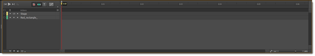
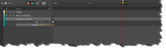
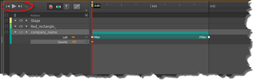
Move the playhead in the timeline to 0:00. The playhead is circled in the snapshot below.
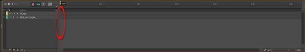
Simply click and drag on the playhead to move it.
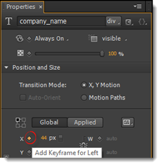
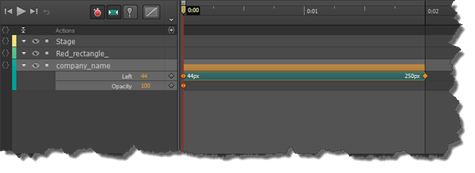
To at the beginning keyframe, go to the Properties panel. Click the empty diamond to the right of the X coordinate. The diamond is a keyframe. Clicking on it inserts a keyframe in the timeline at the position where the playhead is located. We are choosing the X coordinate (instead of the Y) because we want our text to move across the Stage.
If you look at the timeline, you can see that a keyframe has been added.
The Auto-Keyframe and Auto-Transition Modes
Now that you have the starting keyframe, it's time to add the ending keyframe. As we mentioned earlier, you don't have to worry about adding any more keyframes except for the starting and ending keyframes. In other words, you don't have to add keyframes for every second of motion. Edge Animate does this for you using the Auto-Keyframe and Auto-Transition modes. These are turned on by default
The Auto-Keyframe mode is represented by the icon that looks like a stopwatch in the Timeline panel. It is circled below.
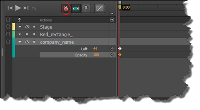
Auto-Keyframe will automatically insert a keyframe whenever changes are made to an element across the timeline. Auto-Transition  makes sure the transitions between keyframes are smooth.
Adding an Ending Keyframe
Now let's add the ending keyframe. To do this, drag the playhead cross the timeline to the point where you want the motion to stop.
As you can see, we put ours at 0:02.
Next, we are going to select our text element on the Stage, since this is the element for which we want to add motion. To do this, press Shift+drag.
Drag the element to where you want it to appear once the motion is complete.
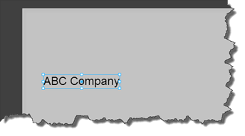
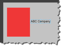
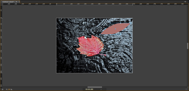
Here is our text element before:
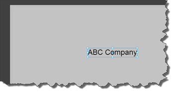
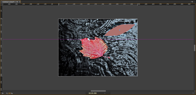
Here it is after we've moved it.
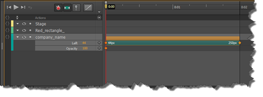
Now look at the Timeline panel:
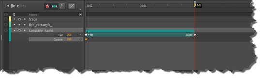
You can see the X coordinate where the motion starts: 44 px. You can also see the end point: 250px.
NOTE: If you want the text to move straight across the screen, make sure your Y coordinate doesn't change.
Now you can move the playhead back and forth between the starting and ending keyframe to see the motion. This is called scrubbing.
Now that we have our motion added, we can unhide our rectangle element.
NOTE: If you wanted, you could also add keyframes for the Y coordinate by using the same steps. You can have keyframes for both the X and Y coordinates at the same time so that your motion goes from side to side and up and down. Each animation that you add to an element will have its own colored bar. The motion we just added has a green bar, as shown below.
Previewing Motion and Animation in Edge Animate
To preview the motion, you can use the playback controls in the Timeline panel. They are circled in the snapshot below.
We've labeled the controls below.
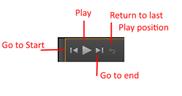
Click the Play  button to play the motion.
Previewing in a Browser Window
To preview in a browser window, go to File>Preview in Browser.
Modifying Motion
Now that we have the starting and ending keyframes, we can add keyframes in between those points if we want. For example, if we want to stop the motion for a half second at a point between the starting and ending frames we could do that.
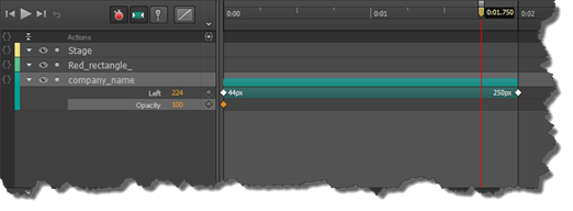
Let's say at 0:01.750 on the timeline, we want the motion to pause.
To do this, we drag the playhead to that point.
Take a look at the Stage. You can see why we chose this point on the timeline to add the new keyframe.
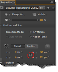
Go to the text element in the Timeline panel. Click the diamond to the right of Left under the text element, as circled below.
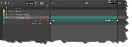
You can see another keyframe is added to the location where you moved the playhead.
This is where the motion will stop. We can see its 224px.
Now, drag the playhead forward to where you want the motion to resume.
Go to the text element in the Timeline panel. Change the value to the right of Left to 224px so it matches the keyframe you just added. Remember, we're making the text element pause on the screen.
Click the diamond to add a keyframe.
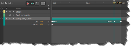
You have now modified the motion.
You can preview it in After Effects or your browser window.
Deleting Keyframes
To delete a keyframe, click on it in the timeline. It will turn to gold.
Right click, then choose Delete.
Speeding Up or Slowing Down Motion
To speed up the motion (make it faster), move the keyframes closer together.
To slow down motion or animation in Edge Animate, move the keyframes further apart.
Let's learn how to do this.
Below we can see the green bar that represents the motion we created in this article.
This green bar is called an animation span.
Place your mouse cursor over the end keyframe. Drag inward to speed up the motion. Drag outward to slow it down.
Moving Keyframes to Delay Motion
Our animation span currently begins at 0:00. Let's say we wanted it to start at 0:01 instead.
To do this, click between the two keyframes.
Your mouse cursor will change to a hand, meaning that you can now move the entire animation span.
While keeping the left mouse button pressed, drag the animation span until the first keyframe is placed at 0:01.
Importing and Creating Elements
This article is the first step in starting to design a composition. You've already created the composition and learned the basics of adding a shape element, then creating motion. However, now we are going to learn to import image elements into Edge Animate, then how to customize HTML elements, such as shapes, for use within your design.
We will discuss how to:
-
Import bitmap and vector images
-
Edit images
-
Resize elements
-
Create HTML elements
-
Customize HTML elements
-
Use rulers and guides to place elements and create your design
More about the Library Panel
The Library panel organizes things that you import into Edge Animate. As you can see in the snapshot below, this includes images, symbols, fonts, audio, video, and scripts.
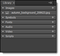
Again, anything imported into Edge Animate can be found in the Library panel even if it's not yet on the Stage. This is where you should look for files after importing them.
Importing Image Files into Adobe Edge Animate
You can import bitmap and vector image files into Adobe Edge Animate, then use those files as elements to create a graphic. Keep in mind that Edge Animate does not give you the ability to draw images as you would in Adobe Illustrator. It also does not give you the ability to edit images as you would in Adobe Photoshop. Instead, you will import artwork that you may have created or edited with those programs, then use them to create graphics in Adobe Edge Animate.
Whenever you import artwork into Edge Animate, the artwork will be stored in the library. You will be able to find any artwork that you import in the Library panel. The artwork will not be saved within your composition. It will be external to your HTML document.
To import artwork, go to File>Import.
You will then see the Import dialogue box.
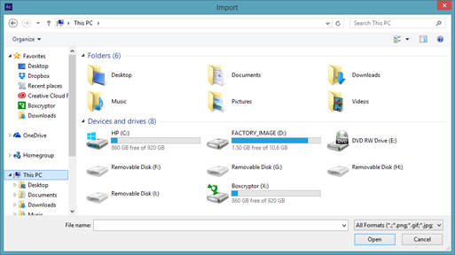
Locate the artwork on your computer. Click to select it. The name of the file will then appear in the File Name field.
Click the Open button.
If we look at the Library panel, we can see our artwork listed under images:
It also appears on the Stage.
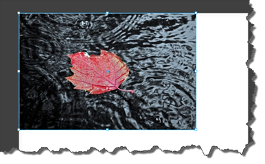
If it doesn't appear on the Stage, you can drag it from the Library panel to the Stage.
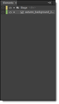
The file also appears in the Elements panel:
Adjusting the Opacity of Images
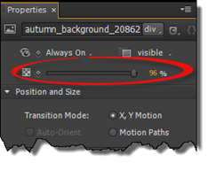
Although Edge Animate doesn't give you the vast editing capabilities like you would find in Photoshop, it does allow you to adjust the opacity of artwork that you have on the Stage.
To adjust the opacity, select the image on the Stage by clicking on it.
Go to the Properties panel.
Resizing Elements
Once you've imported artwork into Edge Animate and added it to the Stage, the artwork is then referred to as an element.
You can resize the elements to fit your composition.
To do this, select the element either on the Stage or in the Elements panel.
Next, go to the Properties panel.
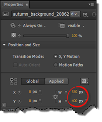
If you want to keep the width and height proportionate, make sure that the Link Width and Height option is enabled, as circled below.
NOTE: It's always a good idea to link the height and width when resizing bitmap images (JPEG, GIF, PNG, etc.) so that the measurements stay proportionate. Bitmap images are resolution dependent, so they may become pixelated if you do not. However, vector graphics are not resolution dependent. You can adjust the measurement for the height, for example, but not the width, and your image will not be distorted.
Now you can click the gold number value for either width or height. Enter a new value.
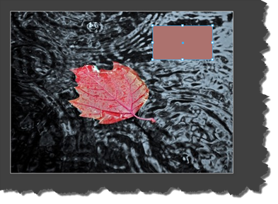
Take a look at our image on the Stage:
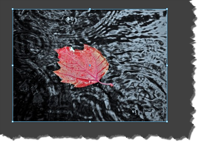
Notice the blue border around our element on the Stage. This is the bounding box. There are white squares that appear at each corner and halfway along each side of our element. These white squares are handles.
You can also resize an object by clicking on the Selection tool in the Tools pane, then hovering your mouse over one of the handles until a two way arrow appears. Drag outward to increase the size of the element. Drag inward to decrease the size. Hold down the Shift key while dragging to constrain proportions.
Creating HTML Elements
HTML elements aren't files that you will see in your library. They aren't imported into Edge Animate either.
Instead, you will create HTML elements. These elements include rectangles, ellipses, and text. These can be modified with CSS. You can also get creative with these to transform them, then use them for things such as buttons in your composition.
Customizing Shape Elements
In the Tools panel, you can choose to drag a rectangle, rounded rectangle, or ellipse shape. We are going to learn how to modify the HTML element and customize it for your composition. The purpose is to turn the simple element into a graphic that you will use in your design. For the purpose of this article, we are going to work with a rectangle.
As you can see, we have added a rectangle shape to our Stage.
Now let's learn how to modify it.
Adding Rounded Corners
You can round all the corners in rectangle, or you can choose to round just one, two, or three. In addition, you can establish how much curve will be added by simply changing the pixel radius of a corner in the Properties panel � or by using the Transform tool.
Let's show you how to do this.
Click on the Transform tool in the Tools panel. It looks like this: 
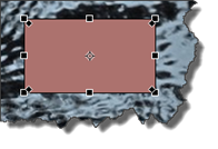
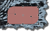
Next, click on the rectangle shape on the Stage.
You will then see a bounding box around the shape. You will also see black diamonds inside each corner of the rectangle, as shown below.
Hover your mouse over one of the black diamonds until your cursor turns into a white arrow.
Click and drag inward.
All four corners of your rectangle will become rounded.
Now go to the Properties panel. Click the triangle to the left of Corners to expand the section.
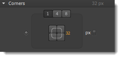
The number in gold (32 in the example above) is displayed in pixel units.
You can change this value to change the curvature of all four corners.
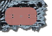
If you want to create asymmetric rounded corners, click on the corners you want to change in the Properites panel, as shown below.

We clicked on the top right and bottom left. As you can see on the Stage, it removed the curve for those corners.
We are going to go back to our shape and drag on the rounded corners again. The reason is we want our shape to resemble a leaf.
Let's look at the Corners section in the Properties panel again.
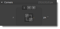
You will see three numeric values at the top: 1, 4, and 8.
-
If 1 is selected, that means all four corners share the same value. The curvature is the same.
-
If 4 is selected, then each corner can have a different value.
-
If 8 is selected, then each corner is allowed to have two values for elliptical curvatures.
Skewing a Shape
The Transform tool in the Tools panel can also be used to skewer a shape.
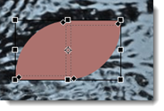
To skewer a shape, click on the Transform tool, then select the shape.
You will then see a dark bounding box with handles appear around the shape.
Hover your mouse over a border until the cursor changes to an icon of two arrows sliding past each other: 
Click, then drag to either the right or left.
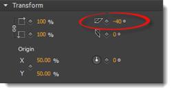
If you go to the Transform section of the Properties panel, you can see the value.
Working with Color, Borders, and Opacity
Now that you have customized the shape of the rectangle, you can also customize the color, border, and opacity.
We are going to use the Select tool in the Tools panel to do this.
Click on the Select tool, then click on the shape.
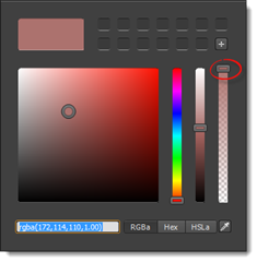
To change the color, click the color chip for background color in the Tools panel.
When you click on it, you will see the Color Picker.

To adjust the opacity of the color, use the slider to the far right:
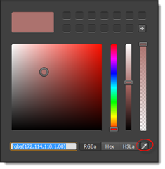
To use a color that already appears on the Stage, click the eyedropper tool located in the bottom right hand corner, as circled below.
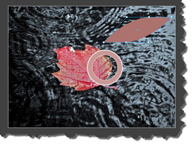
Click on the eyedropper button, then click on the color on the Stage you want to use by centering the circle on that color.
To change the border color of the shape, click the border color chip (located to the right of the background color chip. You will once again see the Color Picker.
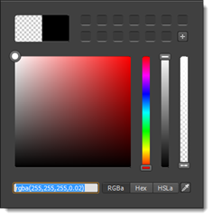
Just as you chose a background color, choose a color for the border. You can set the opacity for the border as well.
Using Rulers and Guides
Rulers and guides help you align elements as you place them on the Stage. Rulers appear across and down the Stage, whereas guides can be moved across the Stage.
Let's learn how to work with them.
To see the rulers, go to View>Rulers.
You can see the vertical ruler to the far left, as well as the horizontal ruler that goes across the top.
The measurement used for the rulers is pixels.
To add guides, click on either the horizontal or vertical ruler, then drag to the Stage.
In the snapshot above, we clicked on the horizontal ruler (top) and dragged down to the Stage.
You should place guides wherever you want to place elements. For example, if you want to place three buttons along the top of the Stage, you could place a guide there to help you align the buttons.
Go to View>Snap to Guides. This will ensure that whenever you move an element close to a guide, the element will snap to it. This makes aligning images using guides a lot easier. Using the button example, whenver you moved a button near the guide, it would snap to the guide, automatically aligning with the other buttons.
In addition:
-
To lock your guides so you can't move them, go to View> Lock Guides.
-
To remove a guide, drag it off the Stage.
-
To hide guides, go to View>Guides.
About Smart Guides
Smart Guides are activated by default. They appear whenever you are using a guide to align elements. Smart Guides help you align two more elements along the same guide.
Let's show you what we mean so it is not as confusing.
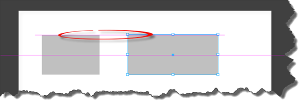
Take a look at the snapshot below.
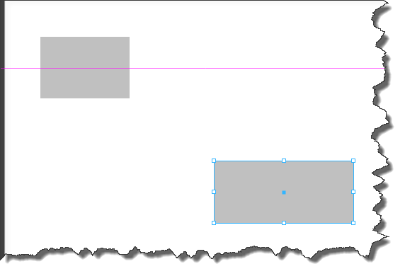
As you can see, we have two rectangles on our Stage. We have aligned one of the rectangles to the guide.
Next, we need to align the second rectangle to the guide. However, we also want to align the second rectangle to the top of the first rectangle.
This is where Smart Guides will help us.
As we drag the second rectangle to the guide, the Smart Guides will appear.
We have circled the Smart Guide in the snapshot below.