Key Terms
o Image
o Virtual image
o Critical angle
o Total internal reflection
Objectives
o Learn how to find the image of an object created by a mirror or lens using geometrical optics
o Explain how light can be "trapped" in the confines of a fiber
Let's Begin!
In this article, we look at some problems and applications associated with geometrical optics. The laws of reflection and refraction allow us to describe electromagnetic waves using rays which are either reflected by a surface or refracted when they cross the surface into a different material. We will look at the creation of images resulting from the use of mirrors and lenses, and we will also consider how fiber optic cables work.
Mirror Images
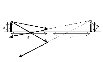
Let's consider some object near a flat (planar) mirror. We'll draw the object as an arrow of a particular length--this allows us to consider both the length and orientation of the image. When we see an object (or its image), we generally are looking at diffuse light, which is electromagnetic radiation (light) that comes from a source (like a light bulb or the sun) and which is scattered in all directions by the object. We need not consider every possible ray (this would be an impossible task); just two different rays will be sufficient. The selection of these rays is largely arbitrary. You may want to try the examples and problems using different rays than those shown to prove that the choice of rays doesn't affect the results. In the diagram below, notice that the object (solid arrow) has a height (length) h and a distance s from the mirror.
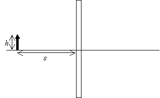
Now, we draw two rays emanating from the point of the arrow. Using the law of reflection, we continue to draw the rays as the travel away from the mirror.
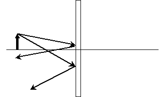
Let's now extend the reflected rays back past the mirror and see where they meet.
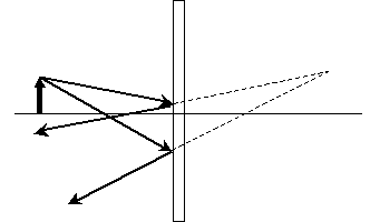
As it turns out, this is the same distance from the mirror and the same height above the horizontal line compared with the solid arrow.
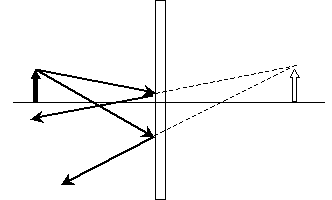
This arrow on the far side of the mirror is the image of the object reflected in the mirror. Because the light rays that seem to emanate from the image do not actually intersect as shown above, however, the image is more correctly called a virtual image. When determining the location of the image, we thus want to determine where the intersection of the two rays is (whether the situation involves mirrors, lenses, or some combination of the two). Note that the horizontal line in the diagram above serves as the bottom of the image in both cases; if you drew a ray along this line, you'd find that it would be reflected back in the opposite direction. Thus, this horizontal line serves as a reference point for the object and image. For a plane mirror, the virtual image is the same distance from mirror as is the object, and it also appears to be the same height.
Practice Problem: Find the approximate location of the image for the following case of an object reflected in a concave mirror.
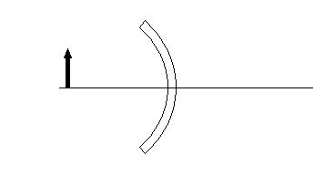
Solution: Let's start by drawing two rays and their reflections, as shown below. We also show the normal (dashed) lines to assist this process.
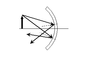
Now we can draw the image. Note that this image is a "real" image (the rays actually intersect-they do not form a virtual image) and that this image is upside down!
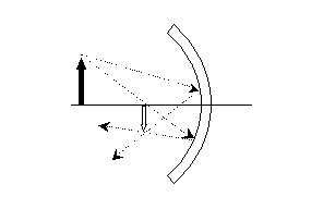
You can see this image inversion by looking carefully at the back of a shiny spoon. If you hold it at the right distance, you will see your face upside down.
The mathematics behind calculating the actual distance and height of an image are not extremely difficult, as long as the mirror is a simple shape (such as planar or spherical). Although we will not get into the math in detail here (for lack of sufficient time), you should already have the tools you need to know how to calculate the correct reflection angles for rays and then determine the intersection (and thus image location) for those rays.
Lenses
We can analyze lenses in the same manner that we analyze mirrors. Let's consider the simple case of a "slab" lens: a rectangular lens composed of a material with some refractive index n2. We'll use the same solid arrow to represent the object, as shown below.
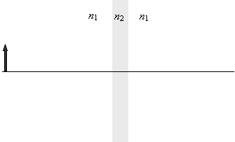
As we did with mirrors, we can draw two rays from the head of the arrow to determine where the image is located. One of the rays we will make perpendicular to the slab for the sake of simplicity, but this choice is not necessary to solve the problem. Let's assume that n2 is larger than n1; as a result, the second ray will refract toward the normal in the material.
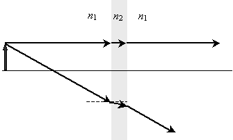
Obviously, the two rays on the far side of the lens do not intersect, so we must extend the second ray back to determine where the virtual image is located.
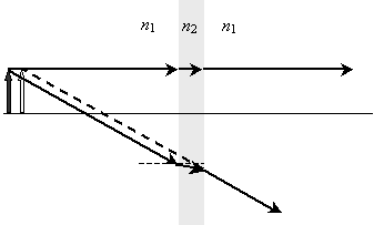
The virtual image is located slightly closer to the lens than is the actual object. Although the case of curved lenses is slightly more complicated (especially the associated mathematics), this case is also more interesting. Although we will not look into it, the same principles of refraction apply.
Fiber Optics
If you've ever been underwater and looked up at the interface of the water with the air, you may have noticed that at some angles you can see what is above the water, but at others you cannot (you may only see a silvery reflection). At certain angles, light is not refracted by an interface between two materials, but it is reflected instead. It is this effect that allows fiber optic cables to carry light pulses down glass "fibers" that are many kilometers in length.
Let's consider light rays "injected" into a glass (n = 1.5) fiber surrounded by air (n = 1.0).
|

Let's calculate ?1 such that ?2 is 90�. In this case, the light ray does not leave the "fiber," but is instead refracted so that it does not exit the fiber. (In the expressions below, n1 is the index of the fiber and n2 the index of the material outside the fiber.)


Notice that we have derived a general formula for ?1; this angle is called the critical angle. Any ray incident at an angle ?1 greater than or equal to the critical angle  will be "trapped" in the fiber--this is called total internal reflection. For angles that exceed the critical angle, the ray is reflected. This reflection continues down the length of the fiber, because the incident angle is maintained by the law of reflection, as shown below. For the indices of refraction in the diagram, the critical angle is about 41.8�.

It is this process that allows fiber optic cables to transmit light pulses without the light "bleeding out" the sides of the fiber!
Practice Problem: A fiber is made of a material with an index of refraction n = 1.2. What is the minimum angle (measured from the normal) with which a ray must be incident on the wall of the fiber to achieve total internal reflection?
Solution: The angle described in the problem is the critical angle. Assuming the fiber is surrounded by air, the ray must have an angle at least equal to ?c. Note that n2 is the index of refraction of the air and n1 the index of the fiber.

Thus, a ray must have an angle of at least 56.4� (measured from the normal to the air interface) to achieve total internal reflection.


