Whenever you create a diagram, you will use a template, even if it's a blank template. You don't have to use a predesigned template if you don't want. In this article, we're going to use a blank template to show you some basic skills you will need to work with shapes in Visio 2016.
The Dynamic Grid
The dynamic grid appears as alignment shaping guides whenever you move a shape near another one. Using the dynamic grid, you can align shapes easily, because the dynamic grid will allow you to snap them into alignment.
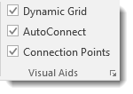
To turn the Dynamic Grid on or off, to the View tab. Put a checkmark beside Dynamic Grid to turn it on. Click to remove the checkmark to turn it off.
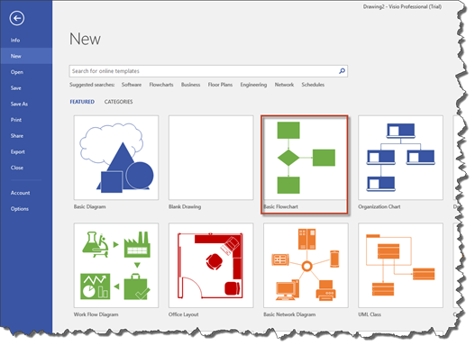
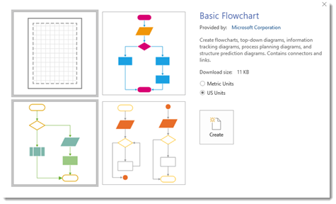
To learn to use the dynamic grid, we first need to open a template. Go to the Backstage view, click New, then select Basic Diagram. Choose your unit of measure, then click Create.
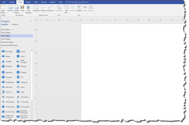
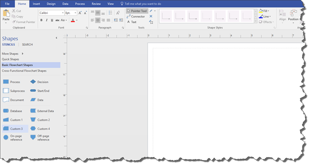
This is what you'll see in your Visio window.
Note that the Shapes window is on the left, and the Drawing window is on the right.
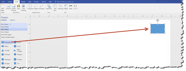
Next, go to the Shapes window. Click Basic Shapes, then locate the Rectangle shape, as highlighted below.
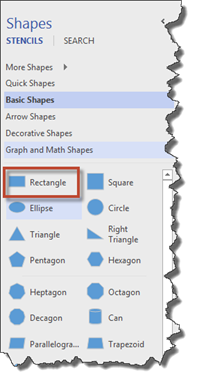
Drag this shape onto your page in the Drawing window. Place it in the upper right hand corner of the page.
If you're having trouble getting the rectangle shape on your page, remember to click on the rectangle shape in the Shapes window. Keep your left mouse button pressed down! With the left mouse button pressed down, move your mouse to the page in the Drawing window. You'll see your mouse dragging the rectangle shape.
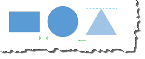
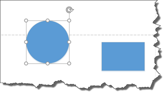
Next, drag a circle shape. Position it to the left of the rectangle. However, once you've dragged the circle and BEFORE you release the mouse button, move it up and down on the page. You'll see the dynamic grid line appear.
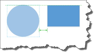
This shows the circle's position relative to the rectangle. The green line that goes across the top of the circle and rectangle shows they are aligned by the top of their shapes. The two-way arrow shows their spacing. If you added another shape, the green arrows would help you create equal spacing between all the shapes.
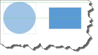
If we move the circle, we can easily change the alignment using the dynamic grid.
In the snapshot below, they are aligned by the center of each shape.
If you want to move the circle back to where you originally dropped it, press CTRL+Z.
You can use the dynamic grid to keep placing shapes on the page, all the while keeping them properly aligned and spaced.
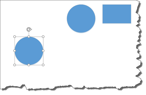
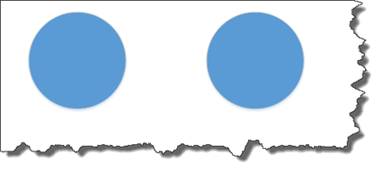
Look at the two shapes we've added to a new drawing below.
The green two-way arrow shows us the spacing between the two shapes.
Now let's add a third shape.
As we drag the third shape, the green two-way arrow appears between the first and second shapes, as well as the second and third, when we have them evenly spaced. Release the mouse button to place the third shape.
NOTE: You can also use the rulers for spacing.
Selecting Shapes
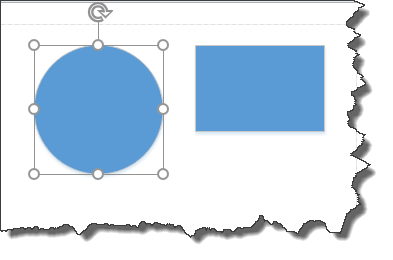
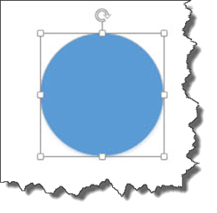
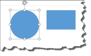
To move or make other changes to shapes in Visio 2016, you must first select the shape. To select a shape, click on the shape. You will see a bounding box appear around a shape when it is selected, as pictured below with the circle.
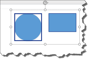
To select multiple shapes, select your first shape as you learned to do above. Press the Shift key and hold it down when selecting all other shapes.
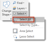
To select all shapes, select a shape, then go to the Home tab, then the Editing group. Click the downward arrow to the right of Select, then choose Select All (Home>Select>Select All).
Copy and Paste Shapes
Chances are, you've used the copy and paste features in other software programs before. However, let's take a minute to explain it again just in case.
Whenever you copy a shape, you copy it to the clipboard. The clipboard stores everything that you either copy from your drawing.
You can then paste that shape into your drawing or into another drawing.
To copy a shape, first select it as we learned to do in the last section.
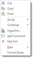
Right click on the shape, then choose Copy from the context menu.
Next, right click in the drawing where you want to paste the shape. Right click again and choose Paste.
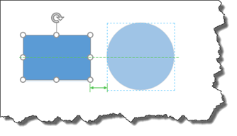
The shape is then pasted into your drawing, as shown below.
The shape that you pasted into the drawing is the one selected. When a shape is selected, you can hold down the left mouse button over the shape until you see a 4-way arrow that looks similar to this:

You can then drag and drop the shape to the location where you want it to appear on the page.
Duplicate Shapes
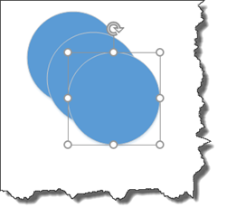
Duplicating shapes sounds more complicated and involved than it really is. To duplicate a shape, simply select the shape, then press CTRL+D. We duplicated our circle twice.
The shape is then duplicated. You can them move the shapes.
Resize and Rotate Shapes
Visio 2016 gives you several ways to resize shapes. Chances are, you're going to want to resize shapes as you use Visio, so learning these methods is important.
You can resize shapes using your mouse, keyboard, or the Size & Position window.
Just be warned that not all shapes can be modified. The only way to know if a shape can be resized is to wait until you try to resize it. You may also discover that shapes that look identical don't behave the same. Again, you won't know until it happens to you.
That said, let's learn how to resize a shape.
Start out by selecting a shape.
You'll then see the box around it. The white squares that you see at each of the four corners and on the sides of the shape are called handles.
You can drag the side handles to change the width or the height.
You can drag the corner handles to change the height and width, all the while keeping the same proportions.
You can rotate a shape by using the rotation handle. This is the circular arrow above the shape.
To do this, hover your mouse over the rotation handle until your mouse cursor is also a circular arrow. Click your left mouse button and rotate the shape while holding the mouse button down. You can rotate it left or right.
Using the Size & Position Window
You can also resize and rotate shapes using the Size & Position window.
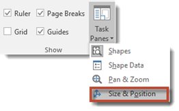
To view the Size & Position window, go to the View tab on the Ribbon. Find the Show group, then click the Task Panes button. Click Size & Position. (View>Task Panes>Size & Position).
You should already have a shape selected.
When you click Size & Position, you'll see this little window appear. It is typically docked on the left side of the Drawing window or to the left of the shape.
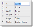
In this window, you can see the coordinates for your shape, as well as the size. You can also see the rotation angle. You can change any of these attributes by clicking on the attribute, then typing in the new one.
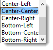
NOTE: "Pin Pos" is the center of rotation for the shape. Imagine a pin through the shape. The pin holds the shape at that point. By default, in the snapshot above, it's Center-Center. You can also choose Center-Left, Center-Right, Bottom-Left, Bottom-Center, or Bottom-Right from the dropdown menu, as pictured below.
Here are our two shapes with the pin position of Center-Center.
Below are the same two shapes with the pin position of Bottom-Right.
Using Lines to Connect Shapes
All shapes in Visio 2016 are either one dimensional or two dimensional -- or 1D or 2D. The shapes we worked with so far are two dimensional. They have an edge and an interior. Another shape you can use to connect other shapes is a line.
Look at the diagram below. You can see the lines connecting the shapes.
Lines are one dimensional shapes. They have endpoints that can be connected to other shapes. In a diagram, you use lines to connect shapes together.
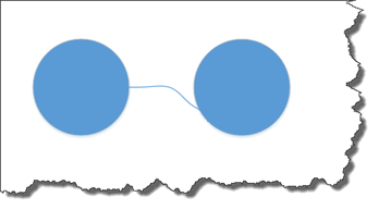
We're going to use these two circles on our drawing. We're going to connect them together.
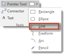
To connect them with a line, we're going to go to the Home tab, then click the Rectangle dropdown arrow. This is to the right of the Pointer tool in the Tools group, as shown below. Select Line.
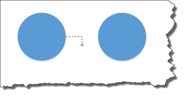
Now, point your mouse near any shape on your page. You'll see black squares appear on the edges and centers of the shape.

These squares are connection points.
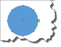
Move the cursor near a connection point. A green square will appear. That square tells you that you can click on it to glue an end of the line to that connection point.
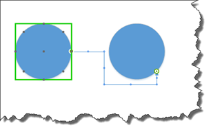
Click the connection point, then drag to a connection point on another shape. Release the mouse button. As you drag toward the other shape, you will see the connection points appear on that shape.
The line is now glued to the edges of the shapes.
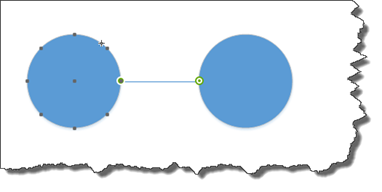
You can tell the line is glued because a white circle appears on the destination end and a green on the original connecting point. If the line wasn't glued, the destination end would have a solid grey square and the starting point would have a white square, as shown below.
Connecting Shapes with Freeform Lines
You can also use freeform lines to connect shapes. Freeform lines can be zigzag or squiggly. To draw a freeform line, go back to the Rectangle dropdown menu, and choose Freeform.
Use it the same way you did the Line tool.
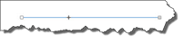
Take a look at the freeform line. You can see little blue dots on the line. These dots are handles that you can use to adjust the shape of the line.
Simply hover your mouse above a blue dot until you see a four-way arrow. Click and drag to change the shape of the line.
You can also use an arc to connect shapes. Simply go to the Rectangle dropdown menu, then select Arc.
You can also use the Pencil.
You can control the path of the line with the pencil.
Using Dynamic Connectors
A dynamic connector is another type of line in Visio. If you use a dynamic connector, Visio adds and removes bends in the line for you. This is based on the position of the shapes and connection points that you are connecting with a line.
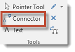
To use a dynamic connector, go to the Home tab, then click the Connector button (Home>Connector).
Next, drag from a connection point of one shape to a connection point on another shape.
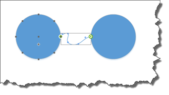
In the snapshot below, you can see we are drawing our line. Note how the line bends as we drag.
We keep drawing our line by dragging the mouse to the destination connection point.
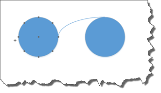
Notice how the dynamic connector added bends in the line that we glued to the destination connection point:
We can now use the handles on the line to reshape the line's path.
Types of Glue in Visio 2016
You glue lines to shapes using connection points. However, you can also glue lines to shapes without connection points.
Dyanmic glue is used to draw lines to shapes that do not have connection points (or glue a line to a part of a shape that doesn't have a connection point).
Static glue is used to glue lines to shapes that have connection points (or that you're gluing to connection points).
About AutoConnect
AutoConnect is simply a fast way to link shapes together using dynamic connectors. In other words, it saves you time when you're creating drawings.
To learn to use AutoConnect, let's switch to a different template. To do this, click the File tab, then New. Click Basic Flowchart, as highlighted below.
Select your unit of measurement, then click the Create button.
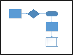
Your basic flowchart opens in Visio.
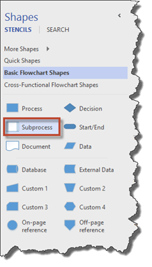
You can look in the Shapes window to see the stencils available for a basic flow chart.
Now, drag a Start/End shape onto the drawing page. You'll see the Start/End shape in the Shapes window.

After you do that, drag some Process and Decision shapes on your page.

Notice that if you click on our mouseover any shape in the drawing that blue AutoConnect arrows appear on the sides of the shape that aren't connected to other shapes.
Go ahead and point to the arrow that's on the right side of the start/end shape. You'll see a preview that shows you the dynamic connector. This is called Live Preview.
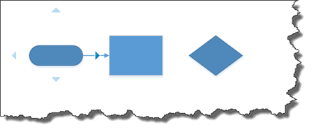
You'll also see a mini toolbar that contains the shapes. We'll talk about it more later.

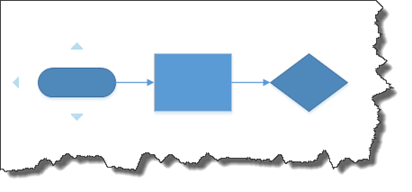
For now, click the AutoConnect arrow to connect the shapes.
Now connect the process shape to the decision shape.
About Quick Shapes
We're about to make creating drawings even quicker and easier for you by teaching you to use Quick Shapes.
When we used AutoConnect, we saw the mini toolbar appear. You can use that mini toolbar to create quick drawings.
Let's see how it works.
Drag a start/end shape onto your page.
Point your mouse to an AutoConnect arrow.
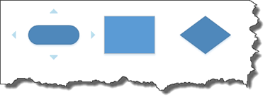
You will see the mini toolbar, as shown below.
When you mouse over a shape in the mini toolbar, it appears on your page. You can see the diamond shape appear on our page below.
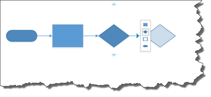
Click on the diamond shape in the mini-toolbar to add it to your page.
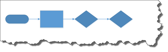
The shapes are automatically connected with a dynamic connector.
AutoAdd and AutoDelete
AutoAdd and AutoDelete are two more tools that Visio gives you to make creating drawings as quick and easy as possible.
-
AutoAdd helps you to arrange your drawings to accommodate new shapes that you may add.
-
AutoDelete removes connectors that still exist after you delete a shape that is linked to another shape.
Let's learn how to use these tools.
You can see our flowchart pictured below.
To use AutoAdd, we are going to drag a Subprocess stencil.
We're going to place the shape on top of one of the dynamic connectors in our drawing.
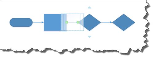
In the snapshot above, we have dragged the shape over a connector, but we haven't released our mouse button yet.
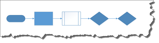
When we release our mouse button, the shape is inserted into our drawing and linked to the shape that comes before, as well as the one that comes after.
To use AutoDelete, we're going to refer to our flowchart again. We're going to delete the Subprocess shape we just added.
To do this, select the shape. Press the Delete key on your keyboard.
Visio deletes the shape as well as the connectors to the shape.
Changing The Colors of Shapes
We are going to create a new drawing before we teach you how to replace shapes in your drawings. So far, we have created a diagram and flowchart drawing. We are doing this so you get experience working with the different templates and types of drawings that Visio 2016 offers.
That said, click the File tab in Visio 2016.
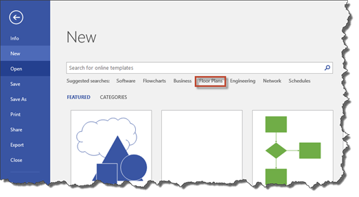
Click New on the left hand side.
Click on the Floor Plans category, as highlighted below.
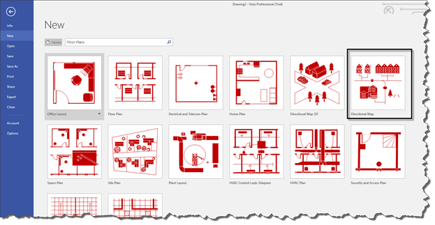
Click on Directional Map.
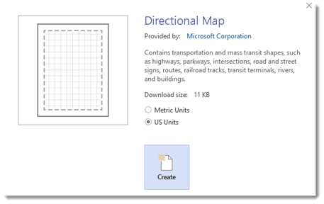
Select your unit of measurement, then click the Create button.
You will then see the stencils you can use for the Directional Map template appear in the Shapes window.
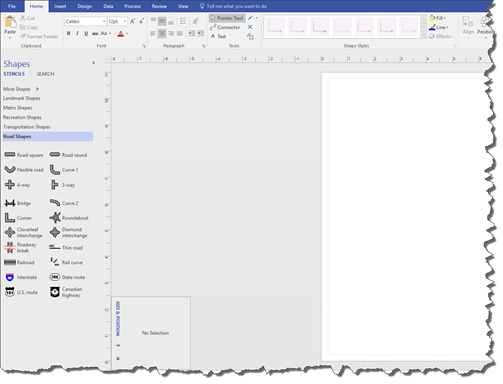
Drag a shape onto the center of the page. Use the Dynamic Grid to drop it in the center.
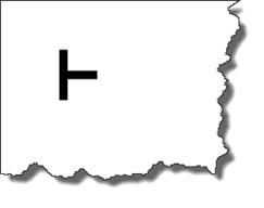
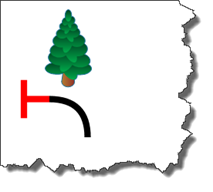
In the snapshot above, we chose the 3-way shape. This shape consists of two lines. It is one dimensional. To change the color of the shape, we simply have to change the color of the line.
Select the shape.
Next, go to the Home tab. Go to the Rectangle dropdown menu again, and select Line.
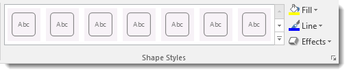
Now let's change the line color. Go to the Home tab and go to the Shape Styles group.
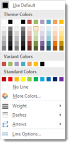
In the Line dropdown menu, change the color to a red.
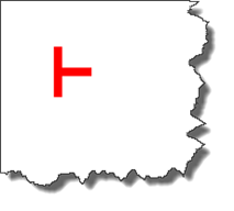
The shape is now red.
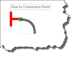
Next, go to the Shapes window and drag more road shapes. We have a three-way shape. You can drag a road square and a curve if you want.
Glue these to the original shape by bringing the shape you're dragging to the other shape until the green square appears.
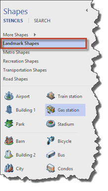
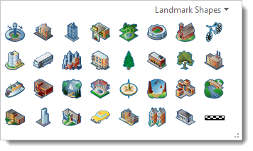
Click Landmark Shapes in the Shapes window.
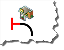
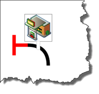
Add a gas station by dragging it onto the drawing.
Note: All shapes have a line color. In a two dimensional shape, the line color is the edge color � or line color. To change the color of the inside of a two dimensional shape, go to the Shape Styles group and select a Fill color in the same way that you chose a line color.
Replacing Shapes
Now, let's learn how to replace shapes in the drawing we just created in the last section.
Click on the gas station to select it.
Go to the Home tab, then click the Change Shape button in the Editing group.
You will see the following dropdown menu.
Choose a new shape from the dropdown menu.