Not all versions of Visio 2016 contain the same network diagram templates. The professional version of Visio contains a detailed network diagram and a basic network diagram; however, that is the only version. If you do not have access to a detailed network diagram, don't worry. The only difference is the detailed network diagram contains more stencils, but you can still create the network diagram you need with the basic template.
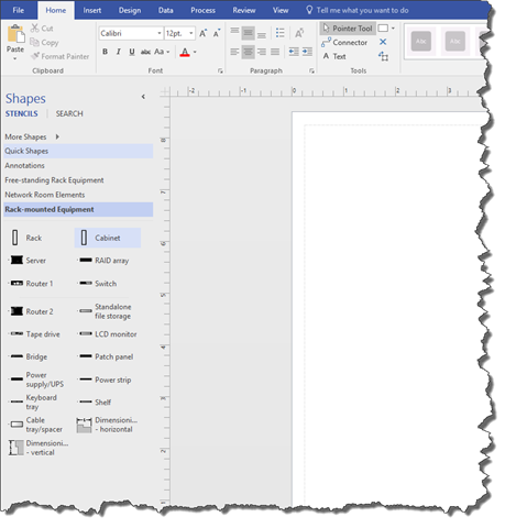
Open the Basic Network Diagram template now by going to Backstage View, then New. Once open, it will look like this:
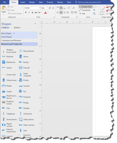
Take a minute to notice the stencils in the Shape window.
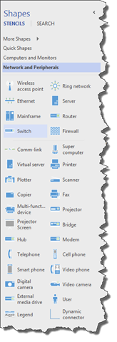
To get started, place an Ethernet shape on the drawing page. You should place it so it's in the center of the page. The Ethernet shape is located in the Network and Peripherals stencil.
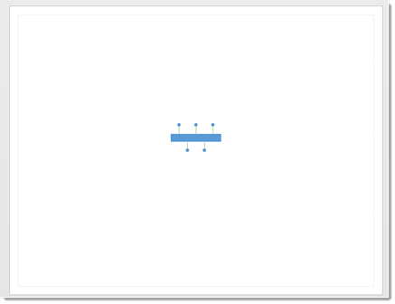
Now, resize the shape by dragging on a side handle so that the shape is four inches long. Use the rulers for the measurement.
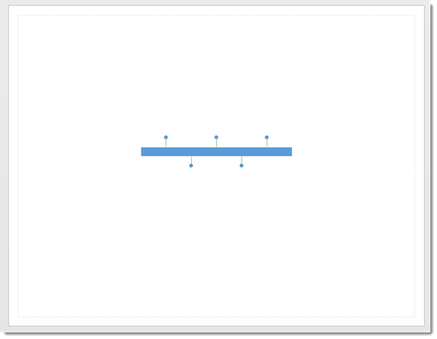
The width bar located on the Status bar (lower left corner of the Visio window) shows you the current length too. You can use that as a guide.

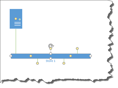
Label the Ethernet Shape "Store 1."
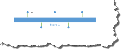
Next, drag a Server shape on the page. Place it above the Ethernet shape and to the left, as shown below.
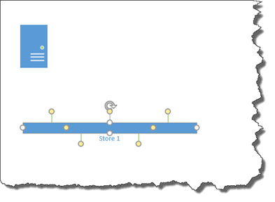
Select the Ethernet shape. Drag a yellow control handle toward the center of the server, as shown below.
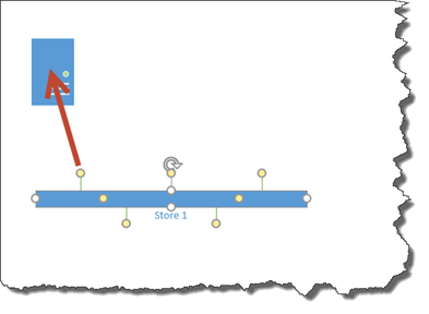
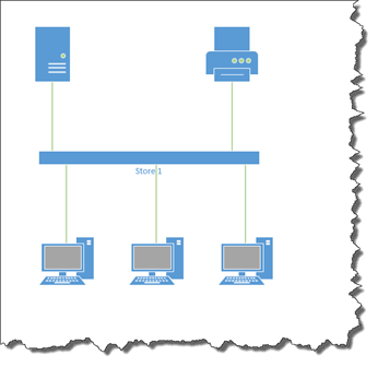
Your drawing will now look like this:
Place a Printer shape above and to the right of the Ethernet shape, then three PC shapes (Computer and Monitors stencil) below the Ethernet shape.
Connect the Ethernet shapes to the shapes you added.
Next, drag a bounding box around all the shapes. Drag and move them to toward the bottom left of the page.
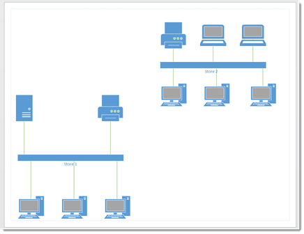
In the upper right side of the page, drag another Ethernet shape.
Drag a size handle to make it the same size as the first Ethernet shape. A green arrow will appear beneath it when it reaches the same width, as shown below.
Label this shape "Store 2".
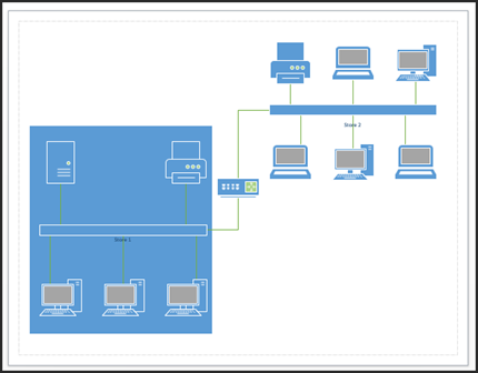
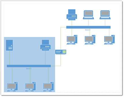
Place a printer shape, two laptop computers, and three computers so it looks like the snapshot below:
Place a router in the center of the page.
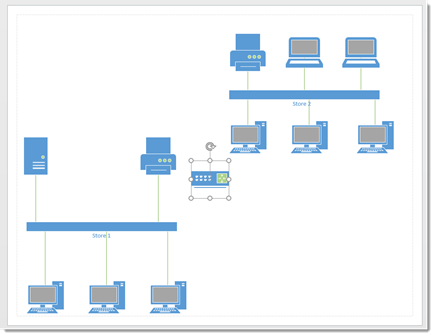
Connect each of the Ethernet shapes to the router.
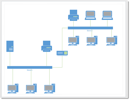
And that's all there is to it! As you can see, creating a basic network diagram isn't difficult at all. Now you can add data to the shapes or link data to the diagram if you wish.
Organizing Network Shapes
Now that you have created your network diagram, you may want to organize the shapes. We're going to teach you how in this section by teaching you to add a background shape, then grouping the shapes in the network.
Let's start by right clicking on the page.
In the mini toolbar that appears, click the dropdown arrow for Drawing Tools, as shown below.
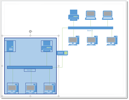
We are going to use the rectangle tool to draw a rectangle around the first network we created.
However, the rectangle is blocking our view of the network.
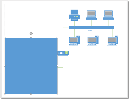
That is because it is in front of the network. We want it to appear as a background behind the network.
To fix this, go to the Home tab, then go to the Send to Back dropdown in the Arrange group. Choose Send to Back from the dropdown menu.
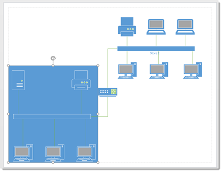
It's still a little too dark, so we're going to change that now.
We're going to select the shape, right click, and choose Format Shape.
The Format Shape pane opens on the right side of the Visio window. This should look familiar to you.
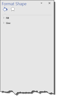
Click the triangle beside Fill.
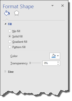
Adjust the transparency so that the rectangle is more transparent.

We adjusted ours to 50%.
Next, we're going to group the shapes. Drag a bounding box around the rectangle and all the shapes.
Go to the Home tab. Click the Group dropdown, and select Group.
You can now follow the same steps with the network labeled "Store 2."
Creating a Rack Diagram
A rack, by definition, is a metal frame that holds devices such as servers, hard disk drives, modems, and etc. It looks like a shelf where components can be stacked on top of each other, then screwed into the front. A rack diagram, in turn, is a drawing of a computer rack that you can then add equipment (shapes in Visio) to.
Let's learn to create a rack diagram, then add the equipment to it.
To start with, let's go to the Backstage View, and open the Rack Diagram template.
When you open this template, you'll notice that it contains four stencils. Three of the four stencils contain equipment and rack shapes.
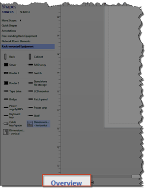
Click the Rack Mounted Equipment stencil in the Shapes window.
Go to the page tab at the bottom of your page in the Drawing window. Double click on the current page name. Type in Overview. Press Enter when you're finished.
Now, right click on the page name (Overview), and select Insert.
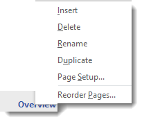
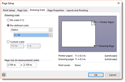
You will then see the Page Setup dialogue box.
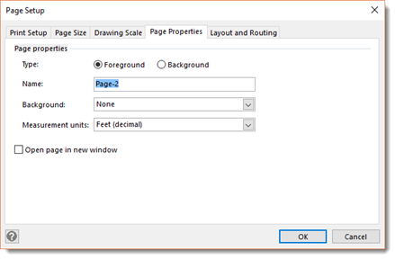
Click on the Page Properties tab.
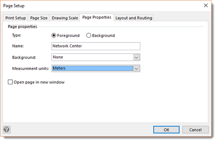
In the Name field, type a name for the new page. We've chosen Network Center.
Click on the Measurement Units dropdown and select Meters. This is the measurements used for the new page.
Now click on the Drawing Scale tab.
Click Pre-Defined Scale.
Select Metric, then 1:10.

Click OK.
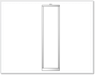
Next, you can drag a rack shape from the Shapes window onto your page. You've already set the measurement units and page scale. Because of this, the rack goes from the top to the bottom margin of the page.
Now that you've drawn your rack, it's time to start adding equipment.
Adding Equipment to Racks
The shapes that you add to your equipment rack look 2-D, unlike the shapes we have worked with thus far. They are 1-D shapes, so you can glue the ends; they just look two dimensional. However, you'll drag them and glue them just the same.
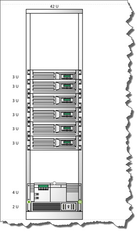
Let's drag a Power Supply and place it at the bottom of the rack.
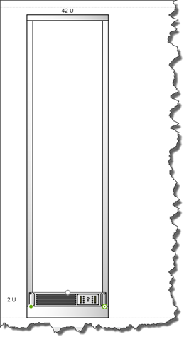
Notice that the sides of the shape can be glued to the rack. This is marked by green. Also notice that the U height appears to the left (2U). The U height is the number of rack units the component occupies.
Next, drag the Server shape and place it in center of the rack.
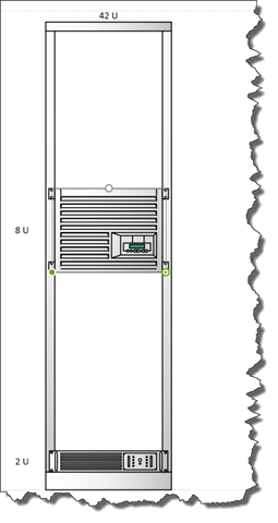
Note the default server shape of 8U. Let's resize it by dragging the handles until it's 3U.
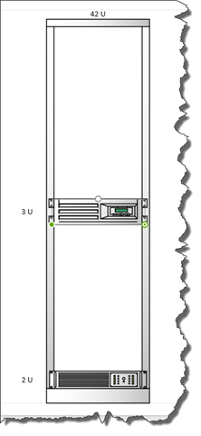
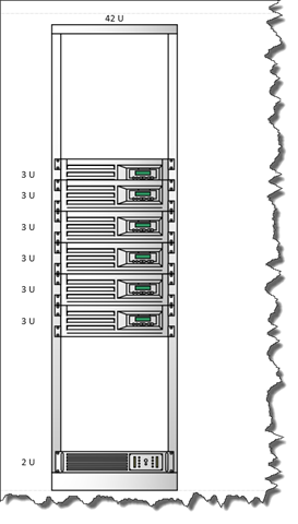
We're going to add more servers to our rack, but we want them all to be 3U. To do this, we're going to select our server, then press CTRL+D (to duplicate the shape) five times for five more servers.
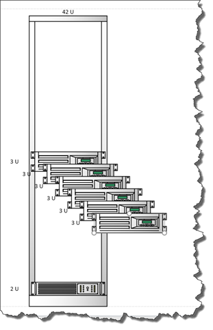
Place these above and below the current server.
Drag a Router shape and place it above the power supply.
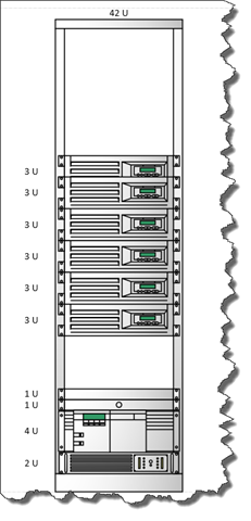
Place a keyboard tray above the router.
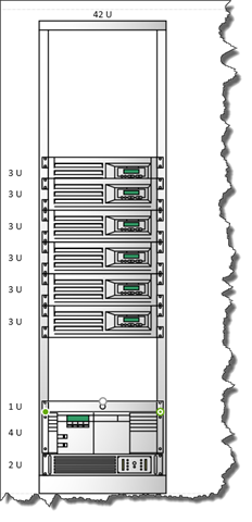
Place a shelf above the keyboard tray.
Place then a monitor (from the Freestanding Rack Equipment stencil) on top of the shelf.
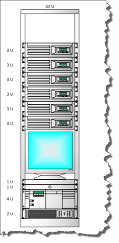
You can now go through and add shape data to the shapes in your drawing. This is an important part of creating a rack diagram because it lets you know where all your equipment is located.
About Drawing Scales
It goes without saying that it would be impossible to draw the actual size of an equipment rack on a page. However, that doesn't mean we don't want actual size representations on the page.
When we create a drawing in Visio, whether it's a rack with equipment or a floor plan for an office, we want to make sure that the shapes we add to our drawing represent actual objects AND accurately represent the amount of space they will inhabit. For example, you might have a drawing scale that's 1":1'. This means that one inch of drawing space equals one foot of actual space.
Changing the Drawing Scale
When we created the rack diagram, we changed the ratio between the drawings and the real equipment. We changed it to 1:10. In that instance, we made the change before we started to create the diagram. However, there may be times when you need to change the drawing scale after you've created the drawing.
Let's learn how to do that.
Go to the page for which you want to change the scale.
Right click on the page tab.
Select Page Setup, then choose the Drawing Scale tab.
Next, select Pre-Defined Scale.
Choose a pre-defined scale or create your own scale values with a Custom Scale.
If you want to change the measurement units, go to the Page Properties tab in the same dialogue box. Go to Measurement Units and choose the unit you want to use.
Customizing Shapes
Using the Rulers and Grid
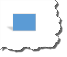
If your shapes are not aligned, it can make even the most organized chart or diagram look bad.
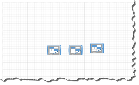
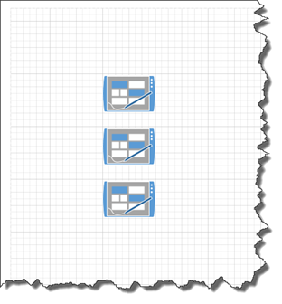
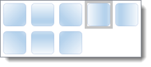
Take a look at the example below:
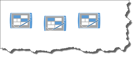
These tablet devices should all be evenly aligned and spaced on the page. The easiest way to align and space them is to use the dynamic grid. However, you can also use the rulers and the standard grid.
The ruler in Visio line the top and left side of your drawing window.
Use the rulers to place objects.
Whenever you select and move a shape, you can see where you're placing it by looking at the rulers.
The top ruler shows you the left edge, center, and right edge of the shape. These are marked by vertical dotted lines.
The ruler on the left shows you the top, middle, and bottom of the side of the shape.
You can also use the rulers to space objects by creating equal space between each object.
To help you place shapes, you can also use the grid.
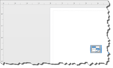
Go to the View tab on the ribbon. Put a checkmark beside the Grid box in the Show group to view the grid.
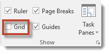
When you put a checkmark in the grid box, this is what you will see on your page:
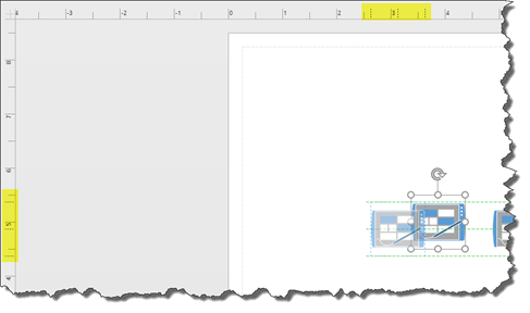
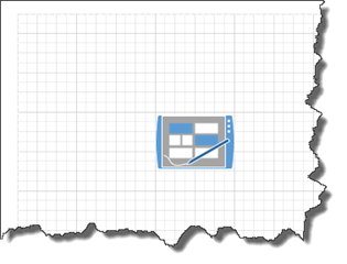
You can use the grid to line up your shapes and create equal spacing between shapes. Simply align a shape to a line on the grid. For example, we're going to align the first tablet device to a line.
We want to align them vertically, so we'll place the left edge of the next tablet against the same line.
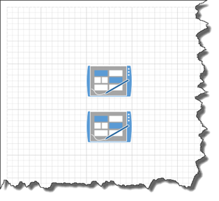
For the third tablet, we'll make sure the spacing is also correct using the grid.
Stacking and Aligning Shapes
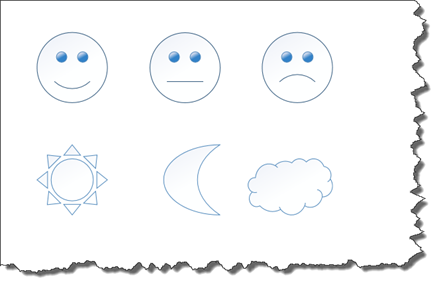
Visio 2016 gives you the ability to align shapes horizontally or vertically when you want to stack them one on top of the other. If you align shapes vertically, you align them to either their left or right edges � or their centers. If you align shapes horizontally, you align them to either their top, middle, or bottom.
Look at the shapes below.
To align the shapes on the top row, drag a bounding box around those shapes.
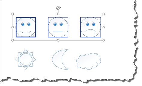
Next, go to Home tab, then click the Align dropdown in the Arrange group.
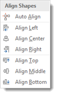
Choose if you want to align left, center, right, top, middle, or bottom.
We're going to choose to align to the right, which means we're going to align the shapes by their right edges.

Positioning Shapes
Having even spacing between shapes is also important in drawings. In order to position shapes so they have even spacing between them, first select the shapes to put a bounding box around them.
Next, go to the Home tab and click the Position dropdown in the Arrange group.
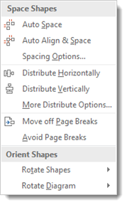
Hover your mouse over Auto Space to see how the anchor shape stays in place, but the other shapes are moved to that the distance between the edges of the shapes is the same. The anchor shape is the furthermost left shape. It will have a darker border than the rest when the bounding box is around the shapes.
Of course, you can click on Auto Space if you'd like to select it.
However, you can also choose to distribute the shapes evenly. If you choose Distribute Horizontally, the two outer shapes are left in place, and the other shapes' spacing is adjusted accordingly.
Applying Themes, Variants, and Quick Styles
Themes, variants, and Quick Styles are aspects that you can apply to your drawings to add and change color, apply special effects, and further customize your drawings to achieve the look and feel you want.
-
A theme includes the colors, fonts, and effects in your entire drawing.
-
A variant is simply a variation of a theme.
-
A Quick Style applies to individual shapes whereas themes and variants apply to the entire drawing.
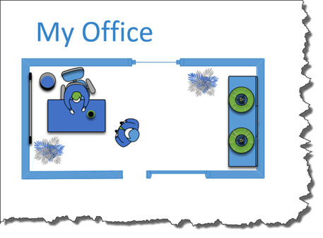
We're going to learn how to apply all three in this section using the office floor plan we created.
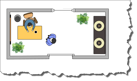
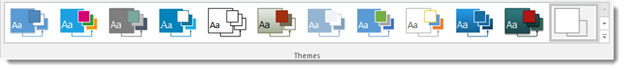
To apply a theme, click the Design tab, and look at the Themes group.
You can hover your mouse over any of these themes to take advantage of Live Preview. Live Preview will show you how the new theme will change the look of your drawing without actually applying the changes.
Let's hover our mouse over a theme.
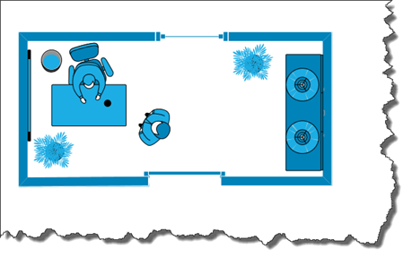
You can see how the new theme changed the colors.
Now, let's add some text to our drawing to see how the theme also applies to fonts. For this, let's go back to our original drawing.
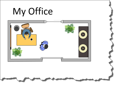
As you can see, we added a horizontal text box and the text "My Office."
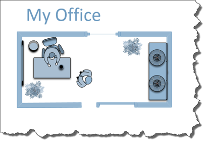
Now let's hover our mouse over a new theme again.
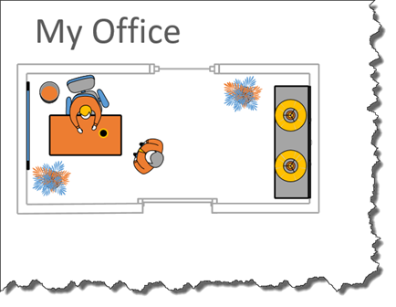
You can see how the font has changed, as well as the colors.
If you want to apply a theme, just click on the theme thumbnail in the ribbon.
We've selected the theme above as our new theme. Now, we're going to apply a variant of the theme.
To do this, go to the Design tab, then the Variants group.
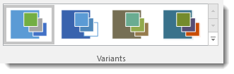
You can hover your mouse over any of the variants to see how they modify the theme. You can also click the downward arrow on the right side of the Variants gallery to see variant options to change the color, effects, connectors, or add embellishment.
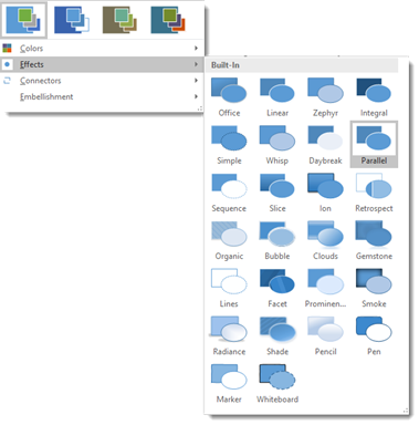
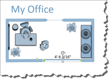
We're going to choose an effect first. Ion is the effect we've chosen.
Next, let's choose a color variant. We've chosen Daybreak.
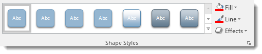
Remember, in addition to themes and variants, we can also apply Quick Styles to individual shapes. Let's apply a Quick Style to the door.
To do this, first select the door.
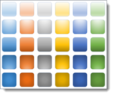
Go to the Home tab, then the Shape Styles group. You can hover your mouse to preview the different styles available to change the look and feel of your shape.
Fill Colors and Patterns
There are two types of colors that apply to shapes. These two types of colors are line and fill colors. Line colors are the borders of your shapes. Fill colors are the colors inside your shapes.
To apply a fill color to a shape, you can right click on the shape, select Format Shape.
You will see the Format Shape pane appear on the right side of your Visio window:
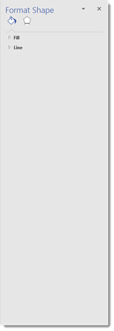
Click the arrow beside Fill to see the options displayed below.
You can choose to apply:
-
No fill
-
Solid Fill
-
Gradient Fill
-
Pattern Fill
Solid Fill
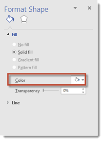
Let's apply a solid fill first by putting a check in the box.
Choose a fill color, as shown below.
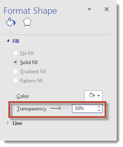
Next, choose the transparency. Set the transparency as a percentage. We're going to set ours at 50%.
If you want to apply a fill to more than one shape, hold down the Shift key while selecting shapes.
Gradient Fill
To apply a gradient fill, check the Gradient Fill box.
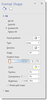
Select a preset gradient.
Choose a direction for the gradient.
Select the angle of the gradient and the gradient stops.
Next, choose a color, as well as the position, transparency, and brightness.
If you want the gradient to rotate with the shape, make sure the "Rotate with Shape" box is checked.
Pattern Fill
A pattern fill does just as the name applies. It fills your shape with a pattern.
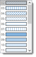
Let's choose Pattern Fill.
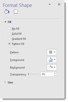
Choose the type of pattern you want to use for your fill.
Next, choose the foreground and background colors. In the patterns above, orange is the foreground color, and white is the background color.
Changing the Line Color and Style
Just as with fills, you can change the line color of shapes in two different ways. You can right click on a shape, then select Format Shape.
When the Format Shape opens on the right, click the triangle beside Line.
From here, you can set your line options, including the type of line. It's a good idea to play around with these options to see what they do. There are endless combinations you can use to customize your line.
Keep in mind that most of these options apply to lines you've drawn on your pages and not the lines that create the borders for your shapes.
You can also go to Home tab, then click the Line dropdown in the Shape Styles group to change the line color.
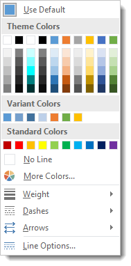
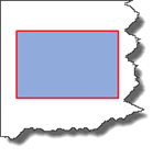
We've changed ours to red.
Adding Special Effects
If you've used other Office 2016 programs, then chances are you're already familiar with special effects. The same special effects that are available in programs such as MS Word are also available to apply to shapes in Visio 2016.
To apply a special effect to a shape, go to the Home tab, then click the Effects dropdown in the Shape Styles group.
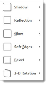
Choose which type of effect you'd like to apply by clicking on the downward arrow beside Effects.
You can then choose how to apply the effect. Below are the options for applying a shadow.
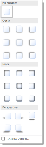
We've chosen to add a shadow to our shape below: