Key Terms
o Direct current (DC)
o Alternating current (AC)
o Frequency
o Transformer
Objectives
o Apply the principles of magnetics and inductors to understand basic transformers
You've probably heard of or seen an electrical transformer near your place of residence: they're utility boxes that convert higher-voltage electricity from your utility company to a lower voltage fit for use in your house (220 volts in America). At this point, we have all that we need to investigate how transformers work. First, however, we must consider two different "types" of electricity.
AC versus DC
You've probably heard the abbreviations AC and DC with regard to electricity. The only real difference between these two is whether the supply voltage is constant with time or changes with time. Direct current (DC) is electricity that has a constant supply voltage (or constant supply current) at all times (assuming no change to the circuit). A battery, for instance, provides direct current electricity: the voltage across the battery's terminals is always constant, at least as long as it still has plenty of remaining stored energy. Alternating current (AC), on the other hand, changes over time. Typically, an AC voltage source is a sinusoidal wave, as the graph below illustrates. The rate at which the voltage changes in this case is called the frequency. The closest example of an AC power source is the power provided by your utility company. The outlets that you plug your computer, television, and other devices into are generally 110V AC outlets with a frequency of 60Hz. (The frequency is determined by the equipment used to generate the electricity.)
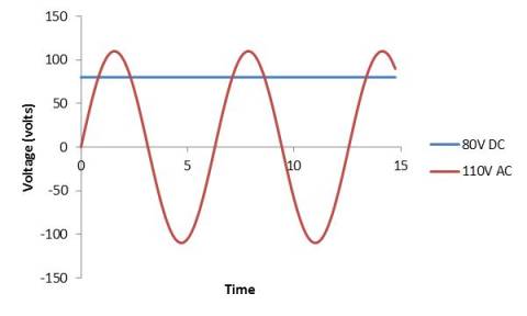
Note that the DC voltage (80V) is constant over time, whereas the AC voltage (110V at its peak) varies sinusoidally (i.e., like a sine wave). Don't let negative voltages trouble you--a negative voltage is no different than if we simply took the battery in a circuit and "flipped it."
Transformers
A transformer is a device that converts one voltage to another--either higher or lower. To understand how a transformer works, we'll look at the case of AC electricity. Recall that an inductor is a device that converts electrical energy to magnetic field energy. Also, recall that a changing magnetic field from an inductor (which results from a changing current) can produce a current in another circuit when that changing magnetic field "passes through" the other circuit. The same logic applies when the other circuit includes an inductor.
For a given current, an inductor produces a magnetic field proportional to the number of loops of wire in the inductor. Similarly, when a changing magnetic field "passes through" the inductor, the current generated is greater when the inductor has more loops than when it has fewer loops. Transformers use these basic magnetic principles to convert from one voltage to another. A transformer simply places two inductors in close proximity, with the inductors designed to produce a certain "output" voltage level relative to the "input" voltage level. (Real transformers are a little more complex, but they are still based on these fundamental concepts.) Not coincidentally, the transformer circuit symbol involves two inductor symbols:
Let's look a little more closely at how a transformer works. If we power an inductor with an AC voltage source (using the circuit symbol below), then the inductor will produce an alternating (changing) magnetic field.
Below, the inductor is drawn a little more explicitly than simply using the circuit symbol.
Now, let's place a second inductor nearby.
Because the supply voltage is alternating (changing), the magnetic field produced by the inductor on the left changes. In turn, because that magnetic field is alternating (and because it "links" to the second inductor), the voltage (or current) produced in the second inductor also changes (at the same frequency). Now, notice that the inductor on the left has more loops than the inductor on the right. As a result, the inductor on the right "receives" less of the energy in the magnetic field, meaning that the voltage across that inductor is lower than the supply voltage. If the number of loops on the rightmost inductor was greater, then the voltage across the leftmost inductor would be greater than the supply voltage.
The precise relationship of current to voltage for a transformer when the other side is "loaded" (with a resistor or other device) is more complicated than this example would suggest. Nevertheless, the basic principles are sound. Note carefully, however, that the transformer is not a power source; as a result, the inductor on the left has the same power (the product of the voltage and current) as the inductor on the right. All that happens in a transformer is that the voltage and current values are changed--the power remains the same.
A Note on Transformer Inefficiency
Ideally, all the magnetic field in a transformer would pass through the loops of the inductors. This is not the case, however--some is outside the inductors, and that field energy is not transferred through the transformer. Thus, transformers are not perfectly (i.e., 100%) efficient. Some measures can be taken to improve efficiency, but inevitably some of the power supplied by the source is "lost" in the voltage conversion process. It's easiest, however, to assume for the sake of simplicity that transformers are perfectly efficient.
Practice Problem: If the peak supply voltage in the circuit below is 10V and the maximum power dissipation in the resistor is 1W, what is the current supplied by the power source when its voltage is at its peak? Assume the transformer is 100% efficient.
Solution: At first, this problem seems extremely complicated, but by applying a number of concepts we have studied, we can find the answer in a logical manner. First, let's note that the peak (maximum) supply voltage is 10V, and this is the same as the peak voltage across the leftmost inductor of the transformer.
We know that the power dissipated by the resistor is 1W. By the rules of current and voltage, we also know that the voltage across the resistor must be the same as that across the rightmost inductor of the transformer. Furthermore, the current through that inductor must also be the same as the current through the loop. In other words, the power received by the rightmost inductor from the leftmost inductor--assuming the transformer is perfectly efficient--is 1W. Thus, the power "dissipated" by the leftmost inductor must also be 1W. Using the power law, then, we can find the current supplied by the power source when the supply voltage is 10V: