?
Key Terms
o Semiconductor
o Diode
o Transistor
o Bipolar junction transistor
o Base
o Collector
o Emitter
o Integrated circuits
Objectives
o Recognize the role of semiconductors in electronic devices
o Examine the basic operation of diodes and transistors
You've probably heard of diodes or transistors: these are devices that underlie virtually all of the electronic gadgets you use. Both of these devices are built using semiconductors, which are materials that have electrical characteristics somewhere between resistors and conductors. The most widely recognizable semiconductor is silicon. The actual semiconductor is typically surrounded by a package that protects the device; if you look at a typical PCB, the semiconductor device packages often look like black, multi-legged bugs. Each "leg" is a conducting pin that serves some function for the semiconductor device: for instance, it can be a power supply input, a connection to "ground," or it may be for some other purpose.

Although we can understand basic electricity-such as in simple resistor and capacitor circuits-using simple physical principles and metaphors (gravity), understanding how semiconductors work is much more complicated. In fact, semiconductor physics relies heavily on quantum theory, which is far beyond the scope of this article! Nevertheless, we can still look at how a couple common semiconductor devices work.
Semiconductor Devices and Ohm's Law
Consider a simple resistor circuit, like the one shown below.
Ohm's law tells us that the current in the circuit I is proportional to the voltage V by the resistance R. Assuming (as we have implicitly done) that R is constant for all voltages, then we can plot a graph showing the current through R as a function of the voltage V across it. Note that the slope of the line is the resistance, R, which in this example is 10?.
Because the resistance is constant, the relationship between voltage and current is linear. But what if the device (which we'll call X in the circuit diagram below) has a resistance that changes with applied voltage V?
In this case, the plot of the current I versus the voltage V could be virtually any shape! But let's take a look at a specific example. A diode is a semiconductor device that does not permit current flow when the voltage drop across it is below a certain threshold (different diodes have different characteristics, but we'll consider one hypothetical example). But when the voltage drop exceeds that threshold, the current increases drastically. Below is a rough representation of the graph of this relationship.
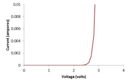
Note that because the curve is non-linear, the resistance changes depending on the voltage. Diodes serve a variety of purposes, such as protecting circuit components that are sensitive to voltage spikes or other power events. Diodes are usually shown in most circuit schematics as some variation (depending on a number of factors, such as the type of diode) of the representation below.

Another semiconductor device, but one that's more complicated and has a wider range of uses, is the transistor. The first transistor design (what's called a bipolar junction transistor, or BJT), instead of having two "terminals" as with power supplies or resistors, has three. These three terminals are called the base, the collector, and the emitter. A diagram (with the commonly used circuit symbol) for one kind of BJT is shown below.
A somewhat simple view of a transistor in one application is that it can act like a "switch": a small current (or voltage) at the base can control a much larger current (or voltage) from the collector to the emitter. Effectively, the base turns "on" or "off" the current flow from collector to emitter. This effect is critical for computers and similar electronic devices, which use binary (ones and zeros, or "on" and "off" states) to perform their tasks. Thus, the voltage at the base controls the resistance from the collector to the emitter, which also allows transistors to be used to amplify electrical signals. Because studying the mechanics of a transistor or how transistors work in a circuit could constitute a study of its own, we won't look further at these devices, except to note that they are the foundation of modern electronics.
Integrated Circuits
The first transistor design was rather bulky and not particularly pleasing aesthetically, but it demonstrated how semiconductors could be used to create devices that can control the flow of current dynamically. Since the first prototype was designed, semiconductor manufacturing technology has come a long way; now, companies can fit billions of transistors onto individual semiconductor chips with dimensions of just centimeters. Obviously, these devices are too small to see individually, but they are what powers so many of the devices you use in everyday life. Semiconductor chips containing a number of interconnected transistors and other silicon devices are called integrated circuits.
Unfortunately, this article does not leave room to investigate all the many fascinating aspects of semiconductors, integrated circuits, and semiconductor device manufacturing. Nevertheless, these areas have all seen stunning progress in less than a century, and they continue to evolve at an impressive rate.
As a final note, some differentiation of the words electrical and electronic is appropriate. Although we have treated these as interchangeable (they generally are the same to laymen), they sometimes have some slightly different meanings. Electrical often applies to devices (or circuits containing devices) like resistors and capacitors, whose characteristics are fixed; electronic often applies to devices (or circuits containing devices) like transistors and diodes, whose characteristics (like resistance) can change according to applied voltages and currents.
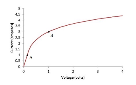
Practice Problem: Determine if the device having the voltage-current curve shown below has a constant or variable resistance and justify your reasoning.
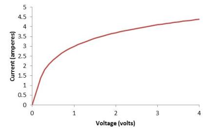
Solution: As we discussed, if a device has a constant resistance, then its voltage-current graph will plot as a line. Since the above is not linear, the corresponding device does not have a constant resistance. One way you can see this more clearly is by applying Ohm's law to a couple different points on the graph. We know that

Consider the two points illustrated below on the graph.